|
Pin Assignment and Description |
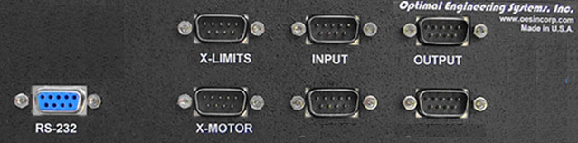
X-Motor
9-pin DB-9, Female Connector
The
X-axis motor should be connected to this connector.
|
PIN |
NAME |
Stepper Motor |
INPUT / OUTPUT |
|
1 |
PHAX+ |
Stepper
Motor Stepper Motor Phase A+ |
OUTPUT |
|
2 |
PHAX- |
Stepper
Motor Stepper Motor Phase A- |
OUTPUT |
|
3 |
PHBX+ |
Stepper
Motor Stepper Motor Phase B+ |
OUTPUT |
|
4 |
PHBX- |
Stepper
Motor Stepper Motor Phase B- |
OUTPUT |
|
5 |
CHSIS |
Connected
to the Chassis |
|
|
6 |
|
Not
Connected |
|
|
7 |
|
Not
Connected |
|
|
8 |
HIGH VOLTAGE |
+15 VDC to +40 VDC |
INPUT |
|
9 |
GND |
+15 VDC to +40 VDC Return |
INPUT |
X-Axis Positive Limit, Negative
Limit, and Home Switch Connection
9-pin DB-9, Male Connector
The X-axis positive, negative and home switches should be
connected to this port.
|
PIN
|
NAME
|
DESCRIPTION
|
Input / Output |
|
1
|
POS-LIMIT-X
* |
X-Axis
Positive Limit Switch Input |
Input |
|
2
|
GND
|
Logic Ground |
GND |
|
3
|
+5 VDC
|
+5 VDC
|
Output |
|
4
|
NEG-LIMIT-X
* |
X-Axis
Negative Limit Switch Input |
Input |
|
5
|
GND
|
Logic Ground |
GND |
|
6
|
+5 VDC
|
+5 VDC
|
Output |
|
7
|
HOME-X
** |
X-Axis
Home Switch Input |
Input |
|
8
|
GND
|
Logic Ground |
GND |
|
9
|
+5 VDC
|
+5 VDC
|
Input |
*
A normally closed switch should be placed between this pin and GND.
** A normally closed switch should be placed between this pin and GND, if the
homing is required.
A pull-up resistor is placed between all inputs and +5
VDC.
RS232 Interface
9-pin DB-9, Male Connector
|
IN
|
NAME
|
DESCRIPTION
|
Input / Output |
|
1
|
|
Not
Connected |
|
|
2
|
DATA-XMT
|
Data
Transmit to PC |
Output |
|
3
|
DATA-RCV
|
Data
Receive from PC |
Input |
|
4
|
|
Not
Connected |
|
|
5
|
GND
|
Logic Ground |
GND |
|
6
|
|
Not
Connected |
|
|
7
|
RESET
|
RESET
Signal from PC to Controller |
Input |
|
8
|
|
Not
Connected |
|
|
9
|
|
Not
Connected |
|
|