|
| |
Motorized Goniometer Stage
|
|
Home
>
Motorized Goniometer Stages
|
|
|
 |
 |
|
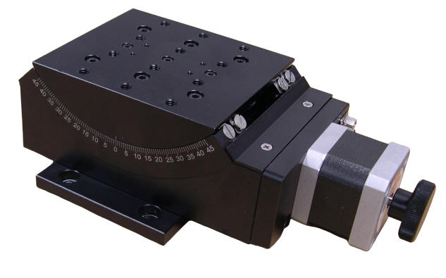
Stepper Motor Driven
Goniometer Stage
|
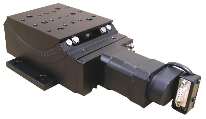
Three Phase Brushless Servo Motor with Quadrature Incremental
Optical Encoder Driven
Linear Goniometer Stage
|
|
|
The
AK120-45
Goniometer
Series
features
precision
ground
worm
gears
with
a
296:1
ratio
and
pre-loaded
cross
roller
guides,
and
+/-
45
degrees
of
travel
with
10
kg
of
load.
The
very
high
resolution
of
0.0006
degrees
(2.16
Arcsec.)
is
realized
when
using
the
standard
Two-Phase
Stepper
Motor
driven
by a
10
micro-steps
per
step
micro-stepping
driver
or
with
the
Servo
Motor
options
and
Quadrature
Optical
Encoders.
.
The
AK120-45
Series
of
goniometer
stages
feature
four
motor
options.
The
-01
option
is
Stepper
Motor
driven.
The
-02
option
(pictured)
is
driven
by a
Three-Phase
Brushless
Servo
Motor
with
a
Quadrature
Optical
Encoder,
the
-03
version
is
DC
Brushed
Servo
Motor
Driven
with
a
Quadrature
Optical
Encoder,
and
the
-04
option
is
Stepper
Motor
Driven
with
the
knob
replaced
with
a
Quadrature
Optical
Encoder
for
position
verification.
The
highest
resolutions,
accuracy,
and
travel
speeds
are
achieved
with
the
servo
motor
options
-02
and
-03.
This
AK120-45
Goniometer
Series
of
Stages
has
a
large
104
mm
long
by
90
mm
wide
table
with
a
precision
pattern
of
mounting
holes
for
precise
location
of
fixtures.
The
height
of
rotation
is
40.5
mm
above
the
surface
of
the
table
and
the
radius
of
rotation
is
67
mm
making
them
ideal
for:
Microscopy,
crystallography,
measurement
of
surgical
cutting
blades,
laser
positioning,
light
measurement,
and
inspection
applications.
This stage requires a
Motion Controller
that can be ordered as a complete plug-and-play system with RS-232, USB, joystick and keypad control.

Video Demonstration
|
|
Specifications
|
Type
|
AK120-45
|
|
Range of Travel |
+/-45 Deg |
|
Table Size |
104 mm x 90 mm
|
|
Gear Ratio |
1 Deg (stage) : 296 Deg (motor) |
|
Height of Rotation Stage |
40.5 mm |
|
Radius of Rotation Stage |
67 mm |
|
Drive Mechanism |
Worm Gear |
|
Travel Guide
|
Crossed-roller Guide |
|
Base Material
|
Aluminum Alloy |
|
Stepper Motor
|
| Typical Phase Current |
1 Amp |
|
DB-9 Male Connector
|
|
Pin Assignment and Description
|
| 1 |
+5 VDC for the Limit Sensors |
| 2 |
CW Limit Switch, Open Collector, Normally Open, Needs Pull up Resistor (1000 Ohms)
|
| 3 |
CCW Limit Switch, Open Collector, Normally Open, Needs Pull up Resistor (1000 Ohms)
|
| 4 |
Return for+5 VDC
|
|
5
|
Not Connected
|
|
6
|
Stepper Motor Phase A+ |
| 7 |
Stepper Motor Phase A- |
| 8 |
Stepper Motor Phase B+ |
| 9 |
Stepper Motor Phase B- |
|
|
|
|
Load Capacity |
10 kg
|
|
Weight
|
2.44 kg (5.5 lb)
|
|
Resolution |
Stepper Motor Driver or Servo Motor Optical Encoder Dependent
approximately 0.0006 Degrees (10 micro-steps per step or 500 Line per Revolution Encoder)
|
|
Maximum Speed |
7 Deg/sec |
|
Typical Positioning Accuracy |
0.05 Degrees |
|
Typical Positioning Repeatability |
+/- 0.01 Degrees |
|
|
|
Ordering
Information
|
Part No.
|
Description
|
Amount
|
|
AK120-45-01
|
Stepper Motor Driven Goniometer Stage,
|
Click to Get a Quote
|
|
AK120-45-02
|
Three Phase Brushless Servo Motor with Quadrature Incremental
Optical Encoder Driven Goniometer Stage,
Table Size 104 X 90 mm
|
Click to Get a Quote
|
|
AK120-45-03
|
DC Servo Motor with Quadrature Incremental Optical Encoder
Driven Goniometer Stage,
Table Size 104 X 90 mm
|
Click to Get a Quote
|
|
AK120-45-04
|
Stepper Motor Driven Goniometer Stage
with 500 Cycles per Revolution Quadrature Optical Encoder
Mounted at the back of the Stepper Motor
,
Table Size 104 X 90 mm
|
Click to Get a Quote
|
|
Related Products
|