|
| |
XY-theta Alignment Stage
|
|
Home
>
XY-theta Alignment Stages
|
|

Stepper Motor Driven
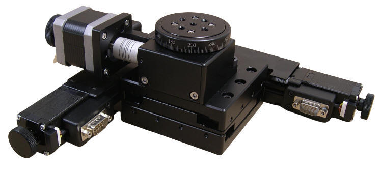
XY-Rotary Alignment Stage, Rotary Stage
Diameter: 60 mm

Stepper Motor Driven
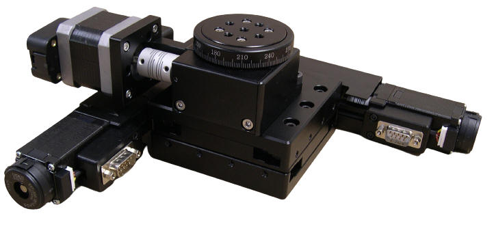
XY-Theta Alignment Stage
with Optical Encoder,
Rotary Stage Diameter: 60 mm
|
|
The XYR-15-60-01 and the XYR-15-60-04 Alignment Stages feature 15 mm (0.58 in.) of travel in both the X and Y axes and 360 Degrees of continuous rotation on the rotary axis.
The new XY-Theta Alignment Stages are driven by Two Phase Stepper Motors featuring 0.25 micron resolution (20 Micro-steps per Step Motor Driver in use). The XYR-15-60-01 has knobs for manual adjustment and the XYR-15-60-04 has 500 Cycles-per-Revolution Quadrature Encoders for position verification.
The X and Y axes have 1 mm-per turn precision lead screws, V-groove crossed roller bearings, and limit switches at both ends.
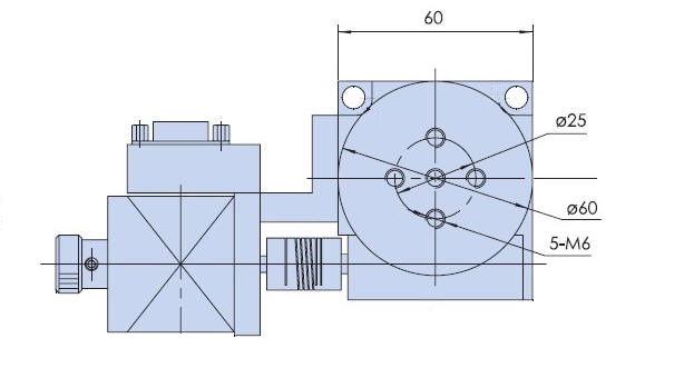
The Theta (rotary) stage is 60 mm (2.362 in.) in diameter with four threaded holes for easy integration of tooling and fixtures, a 90:1 worm gear and precision bearing for smooth travel, and home switch. The compact XYR Alignment stage has a total footprint of 238.0 mm by 238.0 mm (9.370 in. by 9.370 in.) and including the Theta stage is just 87 mm (3.425 in.) high.
The typical applications include: Alignment, testing, inspection, scanning, laser drilling, machining, semiconductor handling, sampling, assembly, and optical applications in industrial, medical and research applications.
The XYR Alignment Stages can be ordered as complete plug-and-play systems with compatible
Motion Controller
with PC interface, joystick, and keypad from OES.
|
Part No.
.
|
Table
Diameter (mm)
|
Gear Ratio
|
Range of Travel
|
Load Capacity (kg)
|
Weight
(kg)
|
|
X
|
Y
|
θ
|
X (mm)
|
Y (mm)
|
θ (Deg)
|
|
XYR-15-60-01
|
60
|
1 mm per Motor Revolution
|
1
mm
per Motor Revolution
|
4
Deg per Motor Revolution
|
15
|
15
|
360 Continuous
|
9
|
2.72 |
|
| |
XY Plane
|
|
Structure
Description
|
Range of Travel
|
15 mm X 15 mm
|
| |
|
|
Actuator Type
|
Lead Screw (1 mm per turn)
|
|
Travel Guide
|
Precision V-groove & Crossed Roller
|
|
X Motor
Y
Motor
Rotary Motor
|
Two Phase Stepper Motor (1.8 Deg)
| Typical Phase Resistance |
3.8 Ohms, Bi-directional |
| Typical Phase Current |
1 Amp |
|
DB-9 Male Connector
|
|
Pin Assignment and Description
|
|
1,2,3,4,5
|
Not Connected
|
|
6
|
Stepper Motor Phase A+ |
| 7 |
Stepper Motor Phase A- |
| 8 |
Stepper Motor Phase B+ |
| 9 |
Stepper Motor Phase B- |
|
|
Base Material
|
Aluminum Alloy
|
|
Surface Treatment
|
Black Anodized
|
|
Load Capacity
|
9 kg
|
|
Typical Accuracy
Description
|
Resolution
|
5microns (Full Step)
0.25 microns (20 Micro-steps per Step Motor Driver in use) |
|
Repeatability
|
+/- 1.5 microns
|
|
Positional Accuracy
|
5 microns
|
|
Accessories
Description
|
|
Optical Encoder
|
| |
Rotary axis
|
|
Structure
Description
|
Range of Travel |
360 Degrees |
| Stage Diameter |
60 mm
|
| Gear Ratio |
90:1 |
| Drive Mechanism |
Worm Gear |
| Travel Guide |
Bearing |
|
Base Material
|
Aluminum Alloy |
|
Surface Treatment
|
Black Anodized |
|
Typical Accuracy
|
|
Resolution
|
0.002 Degrees (10 micro-steps per step)
|
|
Repeatability
|
+/-0.01 Degrees
|
| Positional Accuracy |
0.05 Degrees |
|
Maximum Speed with stepper motor
|
30 Degrees per second |
|
Maximum Speed with servo motor
|
90 Degrees per second
|
Electrical Connection
Two-Phase Stepper Motor (1.8 Deg) Typical
Phase Current: 0.67 Amps for XY axes,
1.0 Amp for Rotary axis
DB-9
Male Connector
,
X and Y axes

|
Pin No.
|
Description
|
|
1 |
+5 VDC for the Limit Sensors |
|
2 |
CCW Limit Switch
The table moves away from the motor
The knob turns counter clockwise
Open Collector
Normally Open
Needs Pull up Resistor (typically 1000 Ohms)
|
|
3 |
CW Limit Switch
The table moves towards the motor
The knob turns clockwise
Open Collector
Normally Open
Needs Pull up Resistor (typically 1000 Ohms)
|
|
4 |
Return for+5 VDC
|
|
5 |
Not Connected
|
|
6 |
Stepper Motor Phase A+ |
|
7 |
Stepper Motor Phase A- |
|
8 |
Stepper Motor Phase B+ |
|
9 |
Stepper Motor Phase B- |
DB-9
Male Connector
,
Rotary axis
|
Pin No.
|
Description
|
|
1 |
+5 VDC
Input
|
|
2 |
Not Connected
|
|
3 |
Not Connected
|
|
4 |
Common
|
|
5 |
HONE (INDEX) Signal
Open Collector
Normally Open
Needs Pull up Resistor (typically 1000 Ohms)
|
|
6 |
Stepper Motor Stepper Motor Phase A+ |
|
7 |
Stepper Motor Stepper Motor Phase A- |
|
8 |
Stepper Motor Stepper Motor Phase B+
|
|
9 |
Stepper Motor Stepper Motor Phase B- |
Stepper Motor Driven Mechanical Drawing
- 60 mm

|
|
Ordering Information
|
Part No.
|
Description
|
Amount
|
|
XYR-15-60-01
|
Stepper Motor Driven
XY-Rotary Alignment Stage, Range of Travel,
X-axis 15 mm, Y-axis 15 mm, Rotary-axis 360 (Deg
Continuous)
|
Click to Get a Quote
|
|
XYR-15-60-04
|
Stepper Motor Driven
XY-Theta Alignment Stage
with 500 Cycles per Revolution Quadrature Optical Encoder Mounted at the
back of the Stepper Motor
,
Range of Travel, X-axis 15 mm, Y-axis 15
mm, Rotary-axis 360 (Deg
Continuous)
|
Click to Get a Quote
|
|
|
|